NEWS
 Home / News / Industry News / How Can JR Series Helical Gear Reducers Adapt to Industrial Transmission Needs and Ensure Stable Operation?
  2025.09.01
 Industry News
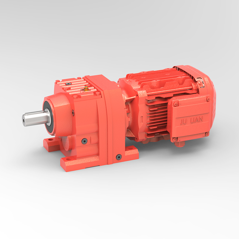
In the transmission systems of industrial equipment such as conveyors, mixers, and CNC machine tools, JR Series Helical Gear Reducers have emerged as widely used core equipment due to their efficient power transmission performance and stable operation. Their core advantage stems from the structural characteristics of helical gears: compared with spur gears, helical gears adopt a spiral tooth design, which results in a larger tooth contact area (approximately 1.5-2 times that of spur gears) during meshing. This design disperses the force on the tooth surface, reduces local wear, and minimizes impact loads during transmission, enabling smoother power transfer.
Through optimized gear module and reduction ratio design, JR Series products can achieve a wide range of reduction ratio adjustments from 0.1 to 1000, adapting to diverse transmission needs—from low-speed, high-torque applications (such as conveyors) to high-speed, low-torque scenarios (such as precision machine tools). Additionally, the gearbox of this series is made of cast iron or cast steel, offering excellent rigidity and heat dissipation. It can maintain stable performance in an ambient temperature range of -20℃ to 40℃, avoiding gearbox deformation or reduced gear meshing accuracy caused by temperature changes. Compared with other types of reducers, JR Series Helical Gear Reducers boast a transmission efficiency of 92%-96%, with lower energy consumption, low maintenance costs, and a long service life (8-12 years under normal maintenance). Thus, they have become a preferred choice in industrial transmission systems that balance efficiency and reliability.
The installation alignment of JR Series Helical Gear Reducers directly affects transmission accuracy and service life. Excessive deviations can lead to poor gear meshing, accelerated bearing wear, and even equipment failures. Before installation, the alignment datum must be clarified: taking the axis lines of the reducer’s input shaft and the motor’s output shaft as the reference, the radial and axial alignment deviations of the two shafts must comply with specifications—the radial deviation (axis offset) should be controlled within 0.05mm, and the axial deviation (end runout) should not exceed 0.02mm. If the deviation exceeds the allowable range, correction is required by adjusting the thickness of the motor base gasket or moving the reducer position.
Professional alignment tools must be used during installation, such as a dial indicator alignment device. Fix the dial indicator on the motor shaft end, rotate the two shafts for one full cycle, and record the maximum radial and axial deviation values. If the deviation exceeds the standard, gradual adjustments are needed until requirements are met. For installation scenarios with coupling connections, the coupling gap must also be controlled: the gap of elastic couplings should be maintained at 0.5-1mm, while rigid couplings require tight fitting without gaps to avoid additional radial forces caused by improper gaps. After installation, a no-load test run (1-2 hours of operation) is necessary to observe whether the reducer runs smoothly and whether there is abnormal noise. Meanwhile, monitor the bearing temperature (normally not exceeding 70℃). Only if everything is normal can the reducer be put into load operation, ensuring that the installation alignment accuracy meets the requirements for long-term stable transmission.
The difference in noise control between JR Series Helical Gear Reducers and ordinary gear reducers (such as spur gear reducers) mainly stems from differences in gear meshing methods and structural design. From the perspective of meshing principles, the helical gears of JR Series reducers adopt “progressive contact” during meshing—the tooth surface contacts gradually from one end to the other, resulting in small meshing impact and significantly reduced high-frequency noise (above 2000Hz) during transmission. In contrast, the tooth surfaces of ordinary spur gear reducers make instantaneous full contact, leading to large meshing impact and obvious “meshing noise,” with noise frequencies concentrated at 1000-3000Hz, which is more perceptible to the human ear.
Practical test data shows that under the same speed (1500rpm) and load (50% rated load), the operating noise of JR Series Helical Gear Reducers is 65-75dB, while that of ordinary spur gear reducers is 75-85dB, with a noise difference of 10-15dB. From the perspective of structural noise reduction design, the gearbox of JR Series reducers adopts a labyrinth seal and stiffener structure, which not only reduces lubricating oil leakage but also absorbs part of the vibration noise. The gear surface undergoes precision grinding (surface roughness Ra≤0.8μm) to reduce noise caused by tooth surface friction. In contrast, ordinary reducers mostly have a simple gearbox structure and lower gear precision (Ra≥1.6μm), resulting in poor noise control effects. In noise-sensitive scenarios (such as food processing workshops and precision machine tool workshops), the low-noise advantage of JR Series Helical Gear Reducers is more prominent, improving the working environment and reducing the impact of noise on equipment accuracy.
The lubricating oil of JR Series Helical Gear Reducers must meet both the needs of “lubricating gear meshing surfaces” and “cooling and heat dissipation.” Improper selection and replacement can easily lead to faults such as gear wear and bearing overheating. Lubricating oil selection should be based on working condition parameters: under normal temperature (-10℃ to 30℃) and medium-low load (≤70% rated load) conditions (such as small conveyors), L-CKC 220 industrial closed gear oil is recommended. It has moderate viscosity, can form a stable oil film on the gear surface, and has good low-temperature fluidity to avoid difficulty in starting in winter. Under high-temperature (30℃ to 40℃) and heavy-load (≥80% rated load) conditions (such as heavy mixers), L-CKD 320 gear oil is required, which has stronger high-temperature oxidation resistance and smaller viscosity changes with temperature, enabling it to withstand higher tooth surface pressure.
Lubricating oil replacement must follow strict cycles: under general working conditions, the first replacement cycle is 1000 hours of operation, and subsequent replacements are every 2000-3000 hours. If working conditions are harsh (such as high dust and high temperature), the cycle should be shortened to every 1500 hours. The replacement process requires standardized operation: first, stop the machine and drain the hot oil inside the gearbox (drain the oil when the oil temperature drops to 40-50℃ to avoid high-temperature scalding or incomplete drainage caused by high oil viscosity); rinse the inside of the gearbox and the gear surface with kerosene or a dedicated cleaning agent to remove residual sludge and impurities; after the cleaning agent dries, add new oil according to the oil quantity marked on the reducer nameplate (the oil level should be at the middle position of the oil level gauge—excessively high oil level can cause increased oil temperature, while excessively low oil level leads to insufficient lubrication); after adding oil, run the reducer under no load for 10-15 minutes, check whether the oil level is normal and whether there is leakage, ensuring that the lubricating oil is evenly distributed to all meshing surfaces and bearings.
Heavy-load conditions (such as mine conveyors and heavy crushers) have extremely high requirements for the load-bearing capacity of JR Series Helical Gear Reducers. Scientific adaptation techniques are needed to ensure safe equipment operation. First, the load torque must be accurately calculated: based on parameters such as the equipment’s rated conveying capacity, material weight, and transmission efficiency, calculate the actual required torque. The rated output torque of the reducer must be 1.2-1.5 times greater than the actual load torque to reserve a safety margin and avoid overload operation—for example, if the actual load torque is 800N·m, a model with a rated output torque ≥960N·m should be selected.
Recommended Products


 EN
EN  English
 Español
 русский


