NEWS
 Home / News / Industry News / K Series Foot-Mounted Hollow Shaft Spiral Bevel Gear Reducer: Complete Industry Guide
  2025.10.23
 Industry News
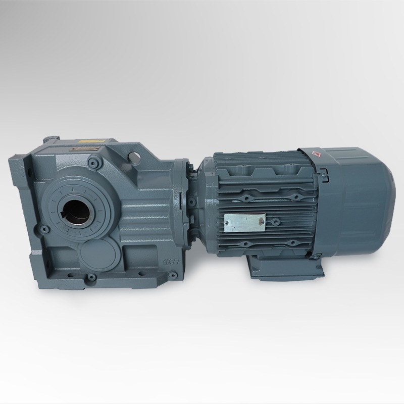
A K Series Foot-Mounted Hollow Shaft Spiral Bevel Gear Reducer is a type of industrial transmission device designed to efficiently convert motor speed into controlled torque output. It combines the advantages of spiral bevel gears, foot-mounted installation, and a hollow shaft structure to create a compact, reliable, and high-performance mechanical solution for power transmission systems.
At its core, this gear reducer operates by using a spiral bevel gear pair to change the direction of rotation—typically by 90 degrees—while maintaining smooth and quiet motion. The spiral bevel design ensures superior load distribution across the gear teeth, reducing vibration and noise compared to traditional straight-cut gears. This makes the reducer highly suitable for continuous-duty applications where stability and efficiency are essential.
The foot-mounted configuration allows the reducer to be securely fixed on a solid base or machine frame, ensuring precise alignment and minimal vibration during operation. This feature also simplifies installation and maintenance, making it a preferred choice in conveyor systems, material handling, and automation machinery.
Another key feature is the hollow shaft output design, which enables direct mounting of driven components such as shafts or couplings. This not only saves installation space but also reduces mechanical complexity by eliminating the need for additional connectors. The result is a more compact system with improved energy efficiency and mechanical reliability.
In summary, the K Series Foot-Mounted Hollow Shaft Spiral Bevel Gear Reducer is an essential component in modern mechanical engineering, offering a balance of power, precision, and durability. Its intelligent combination of bevel gearing and space-saving design makes it a cornerstone in industries requiring smooth torque transmission and long-term operational stability.
| Component | Description | Function in the Reducer |
|---|---|---|
| Spiral Bevel Gears | Precision-cut gears with curved teeth arranged on a 90° axis. | Ensures smooth torque transfer and reduces noise and vibration. |
| Hollow Shaft Output | Central output shaft with an internal bore. | Allows direct connection to driven shafts, reducing installation space. |
| Foot-Mounted Base | Solid mounting frame with alignment holes. | Provides high stability and easy installation on machinery bases. |
| Bearing System | Heavy-duty roller or tapered bearings. | Supports axial and radial loads, ensuring long service life. |
| Sealing Structure | Multi-layer sealing design with oil rings. | Prevents lubricant leakage and contamination. |
| Lubrication System | Oil bath or grease lubrication. | Reduces friction, enhances efficiency, and prolongs component life. |
The spiral bevel gear drive mechanism allows for gradual tooth engagement, resulting in:
| Feature | K Series Spiral Bevel Gear Reducer | Parallel Shaft Gear Reducer |
|---|---|---|
| Gear Type | Spiral Bevel Gears (90° transmission) | Helical or Spur Gears (inline) |
| Transmission Efficiency | 96–98% | 90–94% |
| Output Shaft Type | Hollow Shaft or Solid Shaft | Usually Solid Shaft |
| Mounting Method | Foot-Mounted or Flange-Mounted | Foot-Mounted Only |
| Torque Density | High | Medium |
| Noise Level | Low (due to spiral engagement) | Higher under heavy load |
| Installation Space | Compact (right-angle design) | Larger footprint |
| Maintenance Frequency | Low | Moderate |
| Ideal Applications | Conveyor drives, automation lines, mixers | General machinery and pumps |
The K Series Foot-Mounted Hollow Shaft Spiral Bevel Gear Reducer integrates high-efficiency gearing with a robust support system, ensuring both torque reliability and mechanical precision. Its foot-mounted construction provides structural stability, while the hollow shaft configuration enables direct, flexible coupling to the driven equipment — all within a space-saving, low-maintenance package.
One of the defining characteristics of the K Series spiral bevel gear reducer is its exceptional power transmission efficiency. Thanks to the precision machining of spiral bevel gears, the device can achieve an efficiency rating of 96% to 98%, significantly higher than that of conventional helical or spur gear reducers.
| Parameter | K Series Reducer | Traditional Reducer |
|---|---|---|
| Transmission Efficiency | 96–98% | 90–94% |
| Torque Output (Relative) | High | Medium |
| Thermal Stability | Excellent | Average |
| Energy Consumption | Low | Moderate |
The right-angle configuration of the K Series Foot-Mounted Hollow Shaft Spiral Bevel Gear Reducer enables it to transmit power at 90 degrees, allowing for more compact machinery layouts. Because the output is delivered through a hollow shaft, the reducer can be directly connected to the driven shaft without additional couplings, simplifying mechanical design, reducing installation time, and minimizing failure points.
The K Series spiral bevel gear drive mechanism uses hardened alloy steel gears that are ground to high precision. Combined with the foot-mounted base and optimized bearing arrangement, it can handle high radial and axial loads with stability, ensuring long operational life and consistent performance even under heavy-duty conditions.
The spiral bevel gear design allows for gradual tooth engagement, dramatically reducing noise and vibration levels. This makes the K Series Foot-Mounted Hollow Shaft Spiral Bevel Gear Reducer suitable for noise-sensitive environments such as automated assembly lines, pharmaceutical machinery, and robotic systems.
| Industry | Typical Application | Benefit |
|---|---|---|
| Material Handling | Conveyors, elevators, transfer lines | Compact design, high torque output |
| Automation Systems | Robotics, actuators, motion control units | Precise speed regulation, quiet operation |
| Food & Beverage Processing | Mixers, packaging lines | Hygienic, low-noise operation |
| Mining & Quarrying | Belt drives, crushers | Heavy load capacity, durable construction |
| Textile & Printing | Rollers, feeders, cutters | Smooth motion, accurate speed control |
Despite a slightly higher initial investment, the K Series Foot-Mounted Hollow Shaft Spiral Bevel Gear Reducer offers reduced energy consumption, lower maintenance costs, and extended service life, delivering excellent total cost of ownership (TCO).
| Key Feature | Engineering Benefit |
|---|---|
| Spiral Bevel Gears | High efficiency, smooth torque transfer |
| Foot-Mounted Base | Easy installation, high stability |
| Hollow Shaft Output | Space-saving, direct connection |
| High Torque Density | Handles heavy loads efficiently |
| Quiet Operation | Ideal for automation and precision systems |
| Low Maintenance | Long service intervals, high reliability |
| Reducer Type | Gear Structure | Transmission Angle | Typical Mounting | Output Type | Main Advantage |
|---|---|---|---|---|---|
| K Series Foot-Mounted Hollow Shaft Spiral Bevel Gear Reducer | Spiral Bevel Gears | 90° (Right Angle) | Foot-Mounted or Flange-Mounted | Hollow or Solid Shaft | High efficiency, compact layout, quiet operation |
| F Series Parallel Shaft Gear Reducer | Helical Gears | 0° (Inline) | Foot-Mounted | Solid Shaft | High efficiency, suitable for horizontal drives |
| S Series Helical-Worm Gear Reducer | Helical + Worm Gears | 90° | Foot or Flange | Hollow Shaft | High torque ratio, compact design |
| R Series Helical Gear Reducer | Helical Gears | 0° (Inline) | Foot-Mounted | Solid Shaft | Smooth operation, versatile use |
| Planetary Gear Reducer | Planetary Gears | Variable | Flange-Mounted | Hollow or Solid | Extremely high torque density, compact body |
| Parameter | K Series Spiral Bevel | Helical | Worm | Planetary |
|---|---|---|---|---|
| Efficiency (%) | 96–98 | 94–97 | 70–85 | 95–98 |
| Torque Transmission | High | High | Medium | Very High |
| Noise Level | Low | Low | High | Medium |
| Heat Generation | Minimal | Moderate | High | Low |
| Maintenance Frequency | Low | Moderate | High | Low |
| Feature | K Series Reducer | F Series Reducer | Worm Reducer |
|---|---|---|---|
| Mounting Orientation | Horizontal or Vertical | Horizontal | Horizontal or Vertical |
| Connection Type | Hollow Shaft or Solid Shaft | Solid Shaft Only | Hollow Shaft |
| Space Requirement | Compact | Larger | Compact |
| Installation Ease | Very Easy | Moderate | Easy |
| Feature | K Series | Helical | Worm | Planetary |
|---|---|---|---|---|
| Gear Material | Hardened Alloy Steel | Alloy Steel | Bronze Worm Wheel | Hardened Steel |
| Lubrication Type | Oil Bath or Grease | Oil Bath | Oil Bath | Grease or Oil |
| Maintenance Interval | Long | Moderate | Short | Long |
| Expected Service Life | 20,000+ hours | 15,000+ hours | 10,000+ hours | 25,000+ hours |
| Reliability | Excellent | Good | Moderate | Excellent |
| Parameter | Typical Range | Description |
|---|---|---|
| Transmission Ratio (i) | 8.0 – 250 | Determines output speed relative to input speed. Higher ratios yield slower output and higher torque. |
| Output Torque (Nm) | 200 – 50,000 | Maximum torque capacity depending on model size and gear stage. |
| Input Power (kW) | 0.12 – 200 | Suitable for small automation motors to heavy industrial drives. |
| Efficiency (%) | 96 – 98 | High-efficiency design with spiral bevel gear engagement. |
| Mounting Position | M1 – M6 | Multiple orientations (horizontal, vertical, wall-mounted). |
| Output Shaft Type | Hollow or Solid | Allows direct coupling or standard shaft output. |
| Gear Material | Hardened Alloy Steel | Precision-ground and heat-treated for durability. |
| Lubrication Type | Oil Bath or Synthetic Grease | Ensures smooth gear motion and reduced friction. |
| Noise Level (dB) | ≤ 70 | Quiet operation suitable for noise-sensitive environments. |
| Frame Size | Output Shaft Diameter (mm) | Max Torque (Nm) | Weight (kg) | Typical Input Power (kW) |
|---|---|---|---|---|
| K37 | 25 | 200 | 18 | 0.12 – 0.55 |
| K47 | 30 | 400 | 25 | 0.37 – 1.1 |
| K57 | 35 | 700 | 35 | 0.75 – 2.2 |
| K67 | 40 | 1,300 | 50 | 1.5 – 4 |
| K77 | 50 | 2,700 | 85 | 3 – 7.5 |
| K87 | 60 | 4,800 | 120 | 5.5 – 15 |
| K97 | 70 | 8,000 | 200 | 7.5 – 22 |
| K107 | 90 | 12,000 | 280 | 11 – 30 |
| K127 | 100 | 18,000 | 400 | 15 – 45 |
| K157 | 120 | 30,000 | 650 | 22 – 75 |
| K167 | 140 | 42,000 | 900 | 30 – 132 |
| K187 | 160 | 50,000+ | 1,200 | 37 – 200 |
The output speed can be calculated as:
Output Speed (rpm) = Motor Speed (rpm) ÷ Transmission Ratio (i)
For example, with a motor at 1,500 rpm and a reducer ratio of 50:1:
Output Speed = 1500 ÷ 50 = 30 rpm
| Selection Factor | Engineering Guidance |
|---|---|
| Load Type | Choose gear ratio and torque rating based on continuous, intermittent, or shock loads. |
| Operating Hours | Use high-efficiency models for continuous-duty operation. |
| Installation Orientation | Ensure correct lubrication level for horizontal or vertical mounting. |
| Ambient Temperature | Select oil viscosity suitable for low (<0°C) or high (>40°C) temperatures. |
| Speed Ratio Requirements | Higher ratios for torque amplification; lower ratios for speed-driven systems. |
| Shaft Connection | Use hollow shaft for compact integration or solid shaft for traditional couplings. |
| Maintenance Frequency | Opt for sealed lubrication models in hard-to-access locations. |
Application: Conveyor system for packaging line
Motor Power: 4 kW
Required Output Speed: 30 rpm
Operation Mode: Continuous, 16 hours/day
Calculated Required Ratio = 1500 ÷ 30 = 50:1
Ideal choice: K67 or K77 series with 50:1 ratio for sufficient torque margin and long-term stability.
Regular preventive maintenance ensures continuous operation, reduces repair costs, and prolongs service life.
| Maintenance Item | Frequency | Description | Purpose |
|---|---|---|---|
| Lubrication Check | Every 500 hours | Inspect oil level and quality | Prevent dry friction and overheating |
| Oil Replacement | Every 3,000–5,000 hours | Drain and refill with specified synthetic gear oil | Maintain viscosity and reduce gear wear |
| Seal Inspection | Every 2,000 hours | Check for oil leakage | Ensure housing integrity and cleanliness |
| Bearing Condition Check | Every 4,000 hours | Listen for noise or vibration; replace if needed | Avoid shaft misalignment and efficiency loss |
| Fastener Tightening | Every 1,000 hours | Inspect bolts and mounting screws | Prevent loosening due to vibration |
| Temperature Monitoring | Continuous | Keep operating temperature below 90°C | Avoid oil oxidation and material fatigue |
| Cleaning & Dust Removal | Monthly | Remove external dust or debris | Improve heat dissipation |
| Parameter | Normal Range | Action if Exceeded |
|---|---|---|
| Operating Temperature | 60°C – 85°C | Check oil quality, cooling, and alignment |
| Vibration Amplitude | < 4.5 mm/s | Inspect bearings and gear alignment |
| Noise Level | ≤ 70 dB | Verify lubrication and gear meshing contact |
| Symptom | Possible Cause | Recommended Action |
|---|---|---|
| Excessive Noise | Gear misalignment, oil degradation | Realign gears, replace lubricant |
| Overheating | Low oil level, poor ventilation | Refill oil, improve cooling |
| Oil Leakage | Worn seals or loose fittings | Replace seals, tighten plugs |
| Vibration or Shock | Unbalanced load or worn bearings | Balance load, replace bearings |
| Reduced Output Torque | Gear wear or slip | Inspect gear teeth, replace damaged parts |
The K Series Foot-Mounted Hollow Shaft Spiral Bevel Gear Reducer provides high efficiency (96–98%), smooth torque transmission, and low noise operation, making it ideal for automation, conveyors, and industrial machinery.
| Application Sector | Example Uses |
|---|---|
| Material Handling | Conveyor drives, automated warehouse systems |
| Textile Machinery | Yarn spinners, fabric winders |
| Food & Beverage Industry | Packaging machines, mixers, bottling lines |
| Chemical Processing | Agitators, pumps, blending systems |
| Renewable Energy | Solar trackers, biomass conveyors |
| Mining & Quarrying | Belt drives, crushers, screening machines |
| Feature | K Series Spiral Bevel | Helical Gear Reducer | Worm Gear Reducer |
|---|---|---|---|
| Efficiency | 96–98% | 94–96% | 60–85% |
| Torque Density | Very High | High | Moderate |
| Space Requirement | Compact Right-Angle | Inline, larger footprint | Compact, less efficient |
| Noise Level | Low | Moderate | Low |
| Service Life | 20,000–30,000 hrs | 15,000–20,000 hrs | 8,000–12,000 hrs |
| Mounting Flexibility | Multi-directional | Limited | Horizontal only |
High efficiency reduces wasted energy, minimizes heat generation, and decreases lubricant consumption, supporting sustainability in industrial operations.
Future iterations of the K Series are expected to offer higher torque density, lower noise, and integrated digital monitoring sensors for predictive maintenance.
The K Series Foot-Mounted Hollow Shaft Spiral Bevel Gear Reducer remains a technically advanced, energy-efficient, and cost-effective solution, delivering consistent power, precision, and reliability across industries.
The primary advantage is its combination of high efficiency, compact right-angle design, and hollow shaft output, which allows for smooth torque transmission, low noise, and space-saving installation.
Selection should be based on factors such as required torque, transmission ratio, input power, mounting orientation, and operating environment. Proper alignment, load calculation, and lubrication management are essential for optimal performance.
Regular preventive maintenance includes:
Recommended Products


 EN
EN  English
 Español
 русский


