NEWS
 2025.10.16
 Industry News
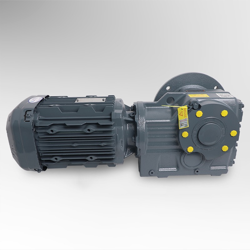
In the field of modern mechanical engineering, efficiency, precision, and space optimization have become the key priorities in power transmission design. The JKAF Series Hollow Shaft Spiral Bevel Gear Reducer represents a refined solution that combines compact structure, smooth torque transmission, and reliable performance. This series is designed to provide right-angle motion transfer with minimal energy loss, making it an ideal component for automation systems and industrial machinery that demand stability and long service life.
Unlike traditional parallel-axis reducers, the JKAF Series Hollow Shaft Spiral Bevel Gear Reducer adopts a right-angle configuration. Through a set of spiral bevel gears, it changes the direction of the drive power by 90 degrees, offering both mechanical efficiency and flexibility in installation. The hollow shaft design further simplifies integration into existing drive systems, allowing direct coupling with driven shafts, thereby reducing the need for additional couplings or connectors.
A hollow shaft spiral bevel gear drive delivers several key advantages:
These features collectively make the JKAF Series Hollow Shaft Spiral Bevel Gear Reducer a preferred choice in industries that require precise power transmission in confined spaces, such as packaging machinery, conveyor systems, and robotic automation.
Another notable advantage of this design is its mechanical stability under high loads. The spiral bevel gear arrangement ensures continuous tooth engagement, leading to smoother operation and reduced vibration. This not only lowers noise levels but also extends bearing life and enhances the durability of the overall gear system.
Furthermore, the right angle hollow shaft bevel reducer design allows engineers to utilize available installation space efficiently. It offers flexibility in system layout — whether mounted vertically, horizontally, or inverted — and its hollow shaft configuration supports through-shaft applications where the output shaft must connect directly to a driven component.
In many applications, the JKAF Series Hollow Shaft Spiral Bevel Gear Reducer acts as a bridge between compact design and high torque capability. Its ability to handle substantial loads while maintaining precise angular transmission ensures consistent performance across varying operational conditions. Whether employed in automated production lines, mechanical transport systems, or custom-built industrial setups, this reducer provides the mechanical precision and operational reliability required by modern industries.
Overall, the JKAF Series Hollow Shaft Spiral Bevel Gear Reducer stands as a technically advanced and efficient solution that reflects the ongoing evolution of motion control systems — merging right-angle efficiency, hollow shaft adaptability, and spiral bevel precision into one integrated drive mechanism.
The JKAF Series Hollow Shaft Spiral Bevel Gear Reducer is a precision-engineered mechanical transmission device designed to convert high-speed, low-torque input into low-speed, high-torque output while maintaining an exact right-angle orientation. It is a key component in many automation and motion control systems where both power efficiency and spatial compactness are critical.
At its core, this type of reducer utilizes a spiral bevel gear mechanism to transmit motion between intersecting shafts, typically at a 90° angle. The spiral bevel gear teeth are designed with a curved profile, allowing for gradual tooth engagement, smoother rotation, and quieter operation compared to straight bevel gear alternatives.
The hollow shaft configuration distinguishes this series from conventional solid-shaft reducers. Instead of transmitting torque through a fixed shaft, the hollow design enables direct connection to the driven machine’s shaft — simplifying alignment, reducing coupling costs, and allowing space-saving installation in tight environments.
The JKAF Series Hollow Shaft Spiral Bevel Gear Reducer is defined by a balance between torque output, compact design, and operational precision. It supports high reduction ratios while minimizing mechanical backlash.
Some of its typical technical characteristics include:
| Model Size | Rated Output Torque (N·m) | Gear Ratio Range | Max Input Speed (rpm) | Efficiency (%) | Hollow Shaft Diameter (mm) | Approx. Weight (kg) |
|---|---|---|---|---|---|---|
| JKAF-40 | 90 – 150 | 1:10 – 1:25 | 3000 | 96 | 25 | 5.8 |
| JKAF-60 | 180 – 350 | 1:15 – 1:35 | 3000 | 97 | 30 | 9.2 |
| JKAF-80 | 400 – 650 | 1:20 – 1:40 | 3000 | 97.5 | 35 | 13.5 |
| JKAF-100 | 700 – 1200 | 1:25 – 1:50 | 2800 | 98 | 42 | 20.1 |
| JKAF-125 | 1000 – 1800 | 1:30 – 1:60 | 2800 | 98 | 50 | 27.3 |
To ensure mechanical integrity and operational precision, the gears within the JKAF Series Hollow Shaft Spiral Bevel Gear Reducer are typically made from case-hardened alloy steel. These gears undergo carburizing, quenching, and fine grinding to achieve optimal surface hardness and minimal tooth deformation.
The housing material is carefully chosen to resist deformation under load and minimize vibration during operation. In many industrial applications, the overall rigidity of the housing is critical in maintaining alignment between the spiral bevel gear set, ensuring that torque transfer remains stable and accurate over long-term use.
In essence, the JKAF Series Hollow Shaft Spiral Bevel Gear Reducer represents a synthesis of mechanical efficiency, space-saving design, and high-precision performance. Its structural composition and engineering design reflect a deep understanding of power transmission demands in modern automated systems, positioning it as a reliable cornerstone of right-angle drive applications across diverse industrial fields.
The JKAF Series Hollow Shaft Spiral Bevel Gear Reducer is designed to deliver outstanding mechanical performance under demanding industrial conditions. Its engineering combines precision gearing, optimized housing geometry, and superior torque handling capacity. Each aspect of the reducer reflects careful consideration of durability, reliability, and space efficiency — key factors in modern automation and power transmission systems.
The JKAF Series Hollow Shaft Spiral Bevel Gear Reducer achieves remarkably high torque density thanks to the optimized geometry of its spiral bevel gears. Unlike conventional straight bevel gearboxes, the spiral tooth profile enables continuous meshing of multiple teeth during rotation. This multi-point engagement significantly increases load-bearing capability while ensuring smooth motion with minimal vibration.
The spiral bevel gear design also reduces impact loads and distributes stress evenly along the tooth surface. As a result, torque transmission efficiency typically ranges between 96% and 98%, depending on gear ratio and lubrication conditions. This high efficiency contributes to lower energy consumption and reduced heat generation during operation — two critical factors for maintaining performance stability in long-duty cycles.
A distinctive advantage of the JKAF Series Hollow Shaft Spiral Bevel Gear Reducer is its compact and modular right-angle configuration. The combination of the hollow shaft and spiral bevel gear layout minimizes the axial length of the drive system, making it particularly suitable for installations with limited space or multiple gear stages.
The compact hollow-bevel gear transmission concept allows direct shaft connection without couplings, which not only simplifies installation but also enhances mechanical alignment. This design reduces vibration sources and prevents misalignment-related failures common in traditional systems.
The use of spiral bevel gears instead of straight-cut gears provides smoother meshing action. The spiral design ensures gradual tooth engagement, effectively reducing shock loads and vibration during rotation. As a result, operational noise is significantly lower — typically below 65 dB under standard load conditions.
Combined with precision machining and advanced bearing systems, the JKAF Series Hollow Shaft Spiral Bevel Gear Reducer maintains consistent rotational accuracy and noise control even at high speeds. This quiet and stable operation makes it well-suited for use in automation, packaging, and food processing equipment, where environmental noise and vibration are strictly regulated.
Efficient heat dissipation is another critical factor in achieving long-term reliability. The gearbox housing of the JKAF Series Hollow Shaft Spiral Bevel Gear Reducer is designed with smooth outer surfaces and high thermal conductivity materials to enhance natural convection cooling.
The internal gear contact surfaces are lubricated through a continuous oil bath or grease system, ensuring that the spiral bevel gears remain fully protected under heavy load. Proper lubrication also helps maintain consistent efficiency and minimizes wear, especially during high-speed or high-torque operations.
| Model | Output Torque (N·m) | Input Power (kW) | Reduction Ratio | Efficiency (%) | Noise Level (dB) | Operating Temperature (°C) |
|---|---|---|---|---|---|---|
| JKAF-40 | 120 | 0.75 | 1:15 | 96.0 | ≤65 | -10 ~ 80 |
| JKAF-60 | 280 | 1.5 | 1:20 | 97.0 | ≤64 | -10 ~ 80 |
| JKAF-80 | 580 | 2.2 | 1:30 | 97.5 | ≤63 | -10 ~ 85 |
| JKAF-100 | 1000 | 4.0 | 1:40 | 98.0 | ≤62 | -10 ~ 85 |
| JKAF-125 | 1600 | 5.5 | 1:50 | 98.0 | ≤62 | -10 ~ 90 |
One of the reasons the JKAF Series Hollow Shaft Spiral Bevel Gear Reducer is widely used in modern mechanical systems is its ability to adapt to diverse load conditions while maintaining consistent mechanical output. Its efficiency remains stable even at variable torque or intermittent duty cycles — a quality particularly valuable in conveyor automation, robotic joints, and servo-driven machinery.
The combination of spiral bevel precision, hollow shaft connectivity, and right-angle transmission makes this series a cornerstone component for engineers seeking performance reliability and compact design integration.
The JKAF Series Hollow Shaft Spiral Bevel Gear Reducer operates based on a sophisticated right-angle torque conversion system, designed to achieve precise motion control while minimizing energy loss. Its power transmission process involves the efficient interaction of spiral bevel gears, high-precision bearings, and a hollow output structure that allows direct mechanical linkage with the driven equipment.
At the heart of the JKAF Series Hollow Shaft Spiral Bevel Gear Reducer lies a set of spiral bevel gears, which serve as the key mechanical elements for right-angle motion transfer. Unlike straight bevel gears, spiral bevel gears feature curved and oblique teeth that engage gradually across the contact area. This ensures smooth torque transmission and continuous load sharing between multiple teeth, greatly reducing impact forces and mechanical noise.
During operation, power enters through the input shaft connected to a smaller spiral bevel pinion gear. This pinion engages with the larger bevel crown gear mounted on the hollow output shaft. The meshing of these two gears changes the direction of power flow by 90 degrees, allowing torque to be transmitted perpendicularly while increasing its magnitude based on the selected gear ratio.
This spiral configuration also improves lubrication retention at the tooth interface, as the curved teeth generate an oil film during rotation, ensuring consistent friction control and wear resistance. The result is a remarkably smooth torque transfer with minimal vibration — a hallmark of the JKAF Series Hollow Shaft Spiral Bevel Gear Reducer.
When rotational energy is introduced to the input shaft, the spiral bevel gear drive transmits torque through gradual rolling contact. The direction of force follows a helical path from the input gear teeth to the output gear surface, effectively dispersing radial and axial loads across the bearings.
This even load distribution is essential for reducing localized stress points, especially under high torque conditions. In contrast to straight-cut systems that often suffer from concentrated pressure zones, the spiral configuration allows the JKAF Series Hollow Shaft Spiral Bevel Gear Reducer to maintain stable performance under fluctuating or shock loads.
The use of tapered roller bearings and precision thrust supports ensures that axial forces generated by the spiral motion are properly absorbed, extending both bearing and gear service life. This feature makes the reducer particularly well-suited for heavy-duty and high-precision operations such as conveyors, lifting devices, and servo-assisted positioning systems.
The hollow core bevel reducer unit offers a distinct engineering advantage by eliminating the need for an intermediate coupling or adapter. Instead, the driven shaft can be inserted directly into the hollow bore of the output shaft, secured by keys, clamps, or shrink discs.
This design improves concentricity and alignment accuracy between the driving and driven elements, reducing transmission losses caused by offset or misalignment. Additionally, the hollow shaft structure minimizes rotational inertia, allowing the reducer to respond rapidly to torque fluctuations — a critical feature for dynamic systems like robotic joints or automated conveyors.
A further benefit is the ability to integrate through-shaft applications. For example, in a dual-drive or pass-through system, the hollow shaft allows an additional driven element (such as a pulley or secondary gearbox) to be connected inline, providing mechanical flexibility without expanding the machine footprint.
| Feature | Spiral Bevel (JKAF Series) | Straight Bevel | Worm Gear |
|---|---|---|---|
| Transmission Efficiency | 96–98% | 90–94% | 70–85% |
| Noise Level | Low (Smooth Tooth Contact) | Medium (Impact Meshing) | Low |
| Torque Density | High (Continuous Load Sharing) | Moderate | High |
| Backlash | Very Low | Medium | Low |
| Maintenance Frequency | Low | Medium | High (Due to Friction Loss) |
| Heat Generation | Minimal | Moderate | High |
| Typical Application | Automation, Robotics, Conveyor Systems | Basic Machinery, Angle Drives | Heavy Load, Low-Speed Drives |
The JKAF Series Hollow Shaft Spiral Bevel Gear Reducer is widely recognized for its adaptability across multiple industrial sectors. Its right-angle transmission design, hollow output configuration, and high-torque efficiency make it ideal for environments where space optimization, smooth power delivery, and long-term reliability are essential.
In automated production lines, conveyor systems require stable motion, high efficiency, and precise synchronization between multiple driven units. The JKAF Series Hollow Shaft Spiral Bevel Gear Reducer excels in these conditions due to its compact design and direct shaft mounting capability.
Modern robotic systems demand gear units capable of handling both dynamic acceleration and precision positioning. The JKAF Series Hollow Shaft Spiral Bevel Gear Reducer meets these needs through its optimized mechanical structure and reduced moment of inertia.
In the material handling industry, gear reducers are required to sustain heavy loads and provide controlled movement. The JKAF Series Hollow Shaft Spiral Bevel Gear Reducer is particularly suited to hoists, elevators, and crane trolleys, where torque amplification and smooth motion are critical.
| Application | Main Function | Preferred Reducer Type | Torque Range (N·m) | Key Benefit |
|---|---|---|---|---|
| Conveyor Rollers | Continuous Linear Drive | Hollow Shaft Spiral Bevel | 100–800 | Compact Right-Angle Mount |
| Crane Trolleys | Travel and Positioning | Spiral Bevel Reducer | 800–1500 | High Torque Stability |
| Hoisting Systems | Vertical Lifting | Spiral Bevel + Worm Combo | 1500–2500 | Precise Load Control |
| AGV Drives | Vehicle Motion | Compact Bevel Reducer | 200–600 | Lightweight Design |
The JKAF Series Hollow Shaft Spiral Bevel Gear Reducer is also applied in renewable energy systems, including wind turbine auxiliary drives, biomass conveyors, and water treatment agitators. In such settings, the reducer must withstand varying loads and environmental stress while maintaining high efficiency and resistance to wear.
| Inspection Item | Frequency | Procedure | Expected Condition |
|---|---|---|---|
| Lubricant Condition | Monthly | Check oil color and viscosity | Clear, free of metal particles |
| Oil Level | Monthly | Verify via sight glass or plug | Within marked level |
| Bearing Noise | Every 3 months | Monitor during operation | No abnormal sound or vibration |
| Mounting Bolts | Every 6 months | Check torque tightness | All bolts secured |
| Seal Integrity | Every 6 months | Inspect for oil leakage | No visible leakage |
| Gear Backlash | Annually | Measure rotational clearance | Within factory tolerance |
| Problem | Possible Cause | Solution |
|---|---|---|
| Abnormal Noise | Misalignment or insufficient lubrication | Re-align shafts; refill or replace lubricant |
| Overheating | Overload or incorrect oil type | Reduce load; switch to high-temperature oil |
| Oil Leakage | Worn seals or excess oil | Replace seals; adjust oil level |
| Vibration | Loose bolts or damaged gears | Tighten fasteners; inspect gear teeth |
| Reduced Output Torque | Excessive wear or backlash | Check gear contact; replace worn parts |
Recommended Products


 EN
EN  English
 Español
 русский


