NEWS
 Home / News / Industry News / What Makes a Helical Gear Hard Tooth Surface Reducer the Right Choice for Heavy-Duty Drives
 2026.11.20
 Industry News
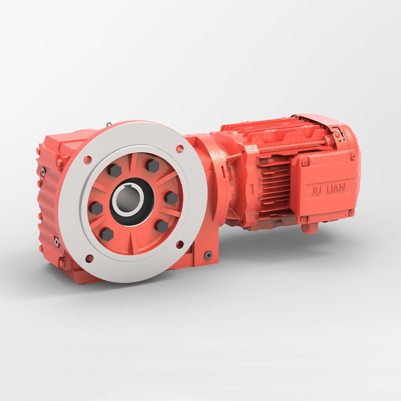
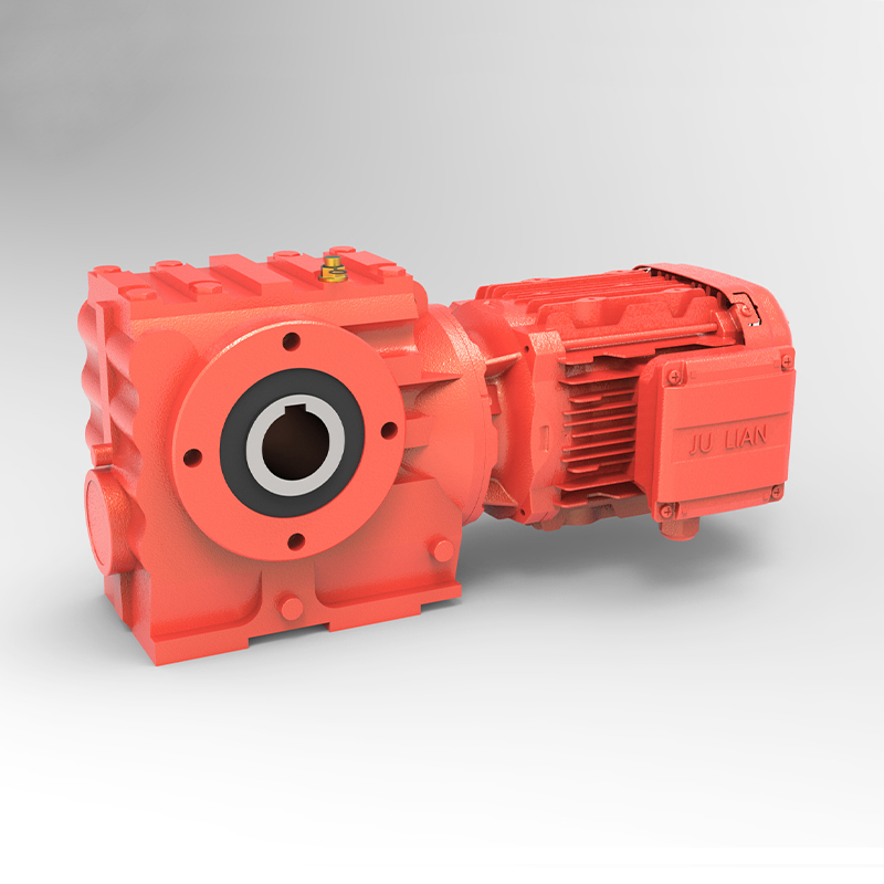
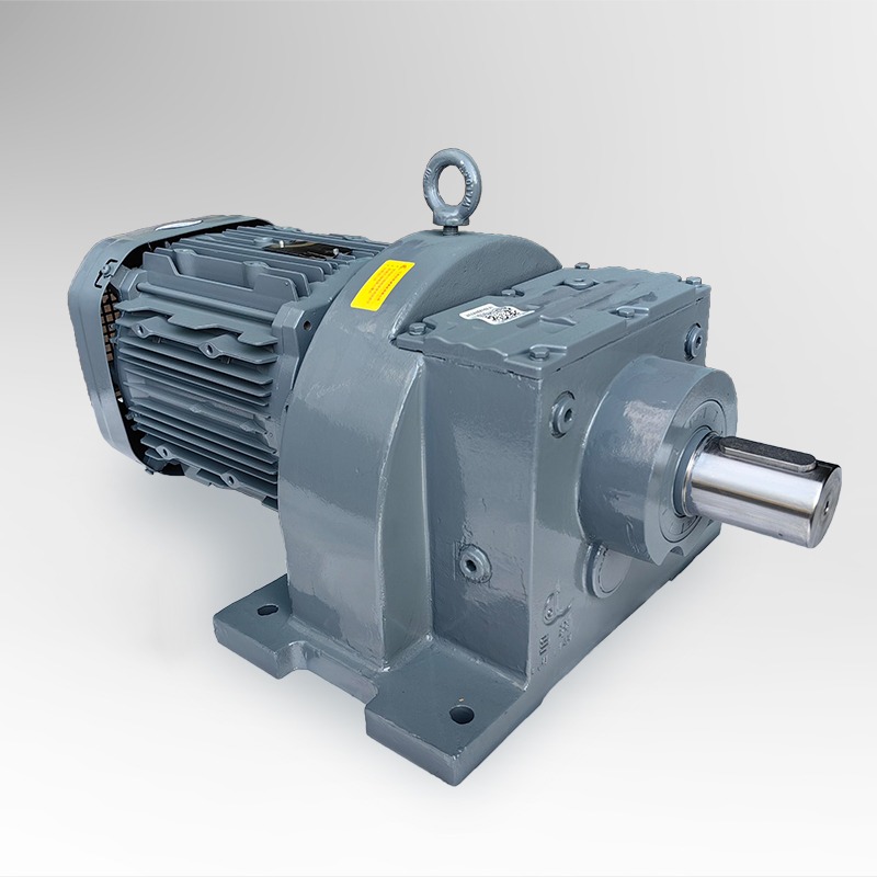
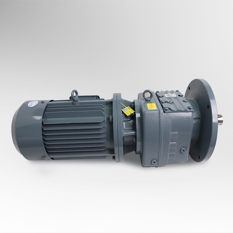
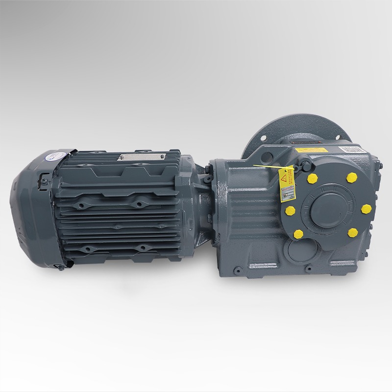
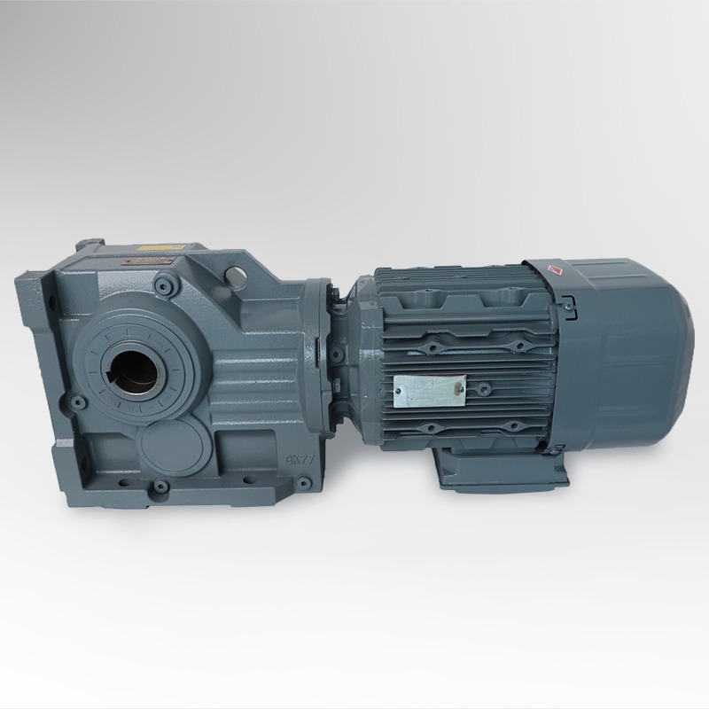
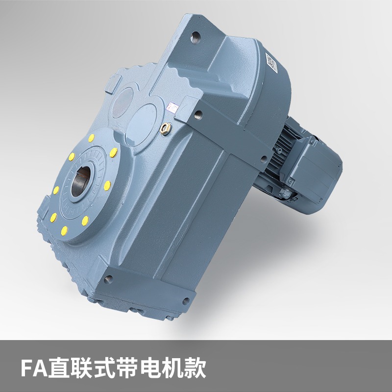
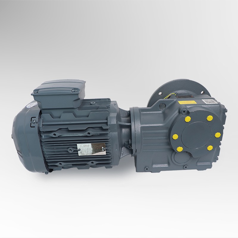
Ask any plant engineer which component causes the most unplanned stoppages in a continuous process line, and the answer often involves the gear drive. Speed reducers sit at the center of conveyors, mixers, kilns, and extruders, and when they fail, the entire line pays the price. That is why a helical gear hard tooth surface reducer has become a standard choice wherever loads are high, duty cycles are long, and maintenance windows are short.
The appeal comes from combining two proven ideas. Helical gearing engages teeth gradually along a diagonal line, which produces smoother motion and quieter operation than straight-cut teeth. Hard tooth surface technology then adds a hardened, wear-resistant working face to those teeth. The result is that the same physical envelope can carry substantially more torque and survive far longer under abrasive or shock-loaded conditions.
Buyers often evaluate these units by price per kilowatt, but experienced specifiers look at total cost of ownership. Downtime, replacement labor, lubricant consumption, and the energy lost to inefficient meshing all accumulate over years of operation. A slightly more expensive drive that runs quietly for a decade can be the cheaper choice by a wide margin.
This article explains how the design works, where it performs best, which performance figures matter, and how to select a unit that fits your application. The goal is practical. After reading, you should be able to frame a specification clearly and recognize the questions that separate a reliable drive from one that will need early attention.
The defining feature of this reducer class is the heat treatment applied to the gear teeth. Blanks are typically made from low-carbon alloy steel, machined close to final geometry, and then carburized so that carbon diffuses into the outer layer of each tooth. The part is subsequently quenched, which transforms that enriched layer into hard martensite while the core remains tougher and more ductile.
In practical terms, hardened tooth flanks commonly reach a surface hardness in the range of 58 to 62 HRC, while the core stays comparatively soft. This combination matters because the surface resists pitting and wear, whereas the core absorbs shock without cracking. Effective case depth usually falls between about 1.0 and 2.5 millimeters, selected according to module size and expected contact stress.
After heat treatment, precision grinding restores the tooth profile and removes distortion introduced during quenching. Grinding is what turns a hardened gear from merely strong into genuinely accurate and quiet. It is one of the most important quality markers to ask about when comparing suppliers, because a hardened but ungound tooth can be noisy and prone to early edge wear.
Helical teeth are cut at an angle to the shaft axis, so contact begins at one end of the tooth and sweeps across the face as the gears rotate. Spur teeth engage across their full width at once. That single difference explains most of the performance gap between the two designs, and it is the reason helical geometry dominates in applications where quiet running and smooth torque transmission matter.
| Aspect | Helical Hard Tooth | Spur Gear |
|---|---|---|
| Meshing smoothness | Gradual, low vibration | Abrupt engagement |
| Noise at rated speed | Lower, often in the 70s decibel range | Higher and more tonal |
| Load capacity per frame size | High, enhanced by hardened flanks | Moderate to high |
| Axial thrust | Generated, must be carried by bearings | None |
| Typical efficiency per stage | 96 to 98 percent | 97 to 99 percent |
Helical gears do generate axial thrust, and the bearing arrangement must be designed to carry it. Spur gears avoid that thrust but pay a penalty in noise and shock loading. For most industrial drives where quiet operation and high torque density both matter, the trade-off favors helical geometry combined with hardened flanks. Spur designs remain sensible for very low speeds or simple, low-cost duties where noise is not a concern.
Numbers on a datasheet are only useful if you know what they represent. Rated torque describes continuous capacity, while peak torque describes what the gears can withstand during brief overloads such as startup. Service factor links the two by accounting for how hard the driven machine works each day. Thermal rating defines how much heat the housing can shed before oil temperature becomes a limiting factor, and that figure often matters more than mechanical capacity in enclosed or hot installations.
Backlash, the small clearance between mating teeth, affects positioning accuracy and shock behavior. Low-backlash designs suit indexing and reversing duties, while standard backlash is adequate for most conveyors and mixers. Always confirm which tolerance band a supplier quotes, because the difference can change how a drive behaves in a reversing application.
Hard tooth surface helical reducers deliver the most value where loads are heavy, starts and stops are frequent, and the environment is demanding. Typical application areas include:
Chemical mixing Conveyor drives Cement and mineral processing Papermaking Grain handling Rubber and plastics extrusion Metallurgy Environmental equipment
In each case, the drive is asked to do more than simply transmit speed. It must absorb shock, survive contamination, and keep running through long shifts, and that combination is exactly where hardened helical geometry earns its reputation.
A mid-size cement plant operated a bulk conveyor driven by a soft-tooth gear reducer. The unit looked adequate on paper, but its gears showed pitting and tooth wear roughly every 14 months. Each replacement required about two days of line downtime, including alignment checks and oil changes.
The plant replaced the drive with a hard tooth surface helical reducer sized with a higher service factor to account for frequent loaded starts. The new installation used an oil bath lubrication system, laser alignment during commissioning, and quarterly oil analysis added to the maintenance routine.
After 30 months, inspection showed no pitting on the active flanks, and annual unplanned downtime for the drive fell from roughly 40 hours to under 10. The lesson was not that one design is universally superior. It was that matching hardness, geometry, service factor, and maintenance discipline together produced the result.
A structured approach prevents most sizing errors. Work through the following sequence before requesting a quotation, and you will communicate far more effectively with any supplier and receive proposals that are directly comparable.
Notice that the sequence moves from load definition to environment. Skipping early steps and jumping straight to a catalog model is the most common reason a unit ends up undersized for real operating conditions.
Most premature failures trace back to a handful of avoidable errors. Watch for these patterns during specification and commissioning.
Even a well-specified hard tooth surface helical gear reducer needs disciplined care to reach its design life. Maintenance does not have to be complicated, but it does need to be consistent.
Oil analysis deserves special emphasis. Rising iron particle counts often appear weeks or months before a gear problem becomes audible, which gives maintenance teams time to plan a controlled intervention instead of responding to an emergency.
Hard tooth surface reducers have carburized and quenched gear teeth with a hardened outer layer, typically around 58 to 62 HRC, and a tougher core. This allows much better resistance to pitting and wear at the same size, which translates into higher load capacity and longer service life, especially in heavy or shock-loaded duty.
Not always, but it is better for most industrial drives that need quiet, smooth torque transmission. Helical gears engage gradually and produce less noise, while spur gears avoid axial thrust and can be simpler at very low speeds. The right choice depends on noise limits, speed, load pattern, and the bearing arrangement you can accommodate.
Consider a hard tooth surface helical design when your application involves frequent starts under load, high shock or reversing torque, long daily running hours, dusty or hot surroundings, or strict noise limits. If the duty is light, intermittent, and quiet-running is not a concern, a simpler unit may be sufficient and more economical.
Operating temperature, lubricant condition, and alignment are the three most influential factors. High oil temperature shortens lubricant life, contamination accelerates wear, and misalignment changes the load pattern on each tooth. Tracking these conditions through regular inspection and oil analysis allows the maintenance interval to be set by actual condition rather than fixed guesswork.
Recommended Products



 EN
 English
 Español
 русский